Sunday, April 22, 2018

Finite-State Machine

# State Machines?


Finite-State Machine (FSM) is a very powerful and simple way of modeling a discrete system. Whilst Petri Nets are used to represent multiple asynchronous processes, FSMs perform a single sequential activity. A Finite-State Machine consists of: a limited number of states, conditions and transitions (from one state to another). 

In a FSM both the output and the next state are functions of the current state and or the inputs. In brief, we can say that our sequential circuit is a Moore Machine if the output is a function only of its current state or a Mealy Machine if the output is a function of the inputs and current state.

In general, FSMs can be implemented using combinational logic and memory. The sequential part of our machine (memory) is used to hold the value of the state the circuit is in. The two combinational parts are utilized to generate the next state and the output. The image below depicts the block diagram for both, Moore and Mealy machines.


Moore and Mealy Machine Block Diagram
Figure 1: Moore and Mealy Machine.


# Representing FSMs


State diagram is the usual way of representing graphically systems with finite states — which is, obviously, the case for FSMs. A State diagram is a direct graph with edges representing the states and vertex representing the transitions. Figure 2 shows the state diagrams for both Moore and Mealy machines.


Representation of Moore and Mealy Machines
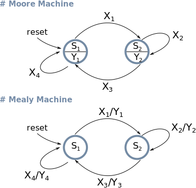
Figure 2: State diagrams for Moore and Mealy Machines. Xn = Input value | Yn = Output value.

# A Simple Traffic Light with Logic Gates


Using the scheme in Figure 1 for the Moore machine, let's design a simple traffic light. This won't be a road intersection (even though can be easily expanded for that purpose) just a simple and easy circuit that displays different timing for each active light for cars and pedestrians.
Let's start with our state diagram.

Traffic Light State Diagram
Figure 3: Each bit in the output represents a different light (Red|Yellow|Green|Red|Green).


As previously mentioned, to indicate the current state we need a way to store its value. In other words, that means we are going to make use of flip-flops to build our state memory
Of course you can use any sort of flip-flop or even other types of memory, however, in order to make things simple, we are going to stick with D-type flip-flops. The excitation of a D flip-flop is very straightforward, it just holds the value of its D-input in a defined portion of the clock (rising or falling edge).

All right, now that we have our state diagram we can build our state transition table. Note that all the states are encoded in binary. The current state is represented in binary form on the output of the flip-flop (Qn) and the next-state in the input (Dn). The encoded format of the states also indicates that we will need to make use of three flip-flops.


Table 1: State Transition Table
State Name State Output Next State
Q0 Q1 Q2 Y0 Y1 Y2 Y3 Y4 D0 D1 D2
RESET 0 0 0 0 0 0 0 0 0 0 1
R0 0 0 1 1 0 0 0 1 0 1 0
R1 0 1 0 1 0 0 0 1 0 1 1
R2 0 1 1 1 0 0 0 1 1 0 0
G0 1 0 0 0 0 1 1 0 1 0 1
G1 1 0 1 0 0 1 1 0 1 1 0
Y0 1 1 0 0 1 0 1 0 0 0 1
- 1 1 1 X X X X X X X X

To derive our boolean expression for each output and each flip-flop we can apply the Karnaugh Map. Figure 4 shows the K-maps for the states and the outputs of our traffic light.

Karnaugh Maps
Figure 4: States and output boolean expressions extracted from K-map.

Finally, all we have to do is place our flip-flops and logic gates from the expressions we got in Figure 4.
Using the website simulator.io I implemented a version of the final circuit we derived. You just have to generate a pulse to make transitions happen.
Traffic Light Schematic
Figura 5: Schematic of our traffic light.

That is it! We made it! But you shouldn't stop here. Finite-State Machines are great and they can be deployed almost everywhere, FPGAs, computer programming, logic gates, etc. Don't forget! Even though the concept of FSM is very simple, it doesn't mean that it is of little importance.

Saturday, March 31, 2018

A Guide to ESP8266 RTOS-SDK


 # Introduction  


Recently, I have been wanting to play around with my — not heavily used — ESP8266 chips. I know, building the environment to program these little chips is not necessarily a hard task. You can simply open your Arduino IDE, install the Arduino core for ESP8266 WiFi chip and then you are ready to write some code and burn your firmware into the chip, no problem.

That was the first thing I did. Using the examples I suddenly was able to blink some LEDs, to print some "Hello World" messages, etc. The Arduino environment is great and has a huge community around it. However, it is just one of many software platforms available for the ESP8266.

Essentially, the Software Development Kits (SDKs) for the ESPs can be classified into: NON-OS SDK and RTOS SDK. The former provides APIs for functionalities such TCP/IP stack, hardware interfaces and it uses timers and callback functions to perform events and tasks. The later uses a Real-Time Operating System (RTOS) as small-scale operating system to manage multi-threading.

I really wanted to experiment with the official ESP8266 RTOS SDK as it is the native way of programming these chips and supports FreeRTOS. But first, I had to install everything.
  

# Building the Compiler


This step is not that hard, you just clone and make the esp-open-sdk. All the requirements and dependencies are very well documented, just follow the steps given in the repository. Do not forget to keep the command to set PATH variable  at the end of build process

Remark: when building the compiler I had to unset LD_LIBRARY_PATH system variable. The script that builds the compiler will complain if the variable is set.

$ unset LD_LIBRARY_PATH

# Hello World and Blink


First, clone the RTOS SDK repository.

$ git clone https://github.com/espressif/ESP8266_RTOS_SDK.git

Copy the "project_template" folder to your workspace.

$ cp -R ESP8266_RTOS_SDK/examples/project_template YOUR_WORKSPACE_PATH/hello_project

Open  ./gen_misc.sh file (or .bat for Windows). Insert the PATH command you previously saved and modify the SDK_PATH and BIN_PATH variables. Save it.

$ export PATH=YOUR_PATH_TO/esp-open-sdk/xtensa-lx106-elf/bin:$PATH
$ export SDK_PATH=YOUR_PATH_TO/ESP8266_RTOS_SDK
$ export BIN_PATH=YOUR_PATH_TO/ESP8266_RTOS_SDK/bin

In this example we will need to use the uart and gpio APIs. To use them, we need to build the driverlib.

$ cd ESP8266_RTOS_SDK/driver_lib
$ ./make_lib driver

Copy the driver folder to your project folder.

$ cp -R ./driver YOUR_WORKSPACE_PATH/hello_project

Go back to the "hello_project" folder and modify the Makefile.
Add the "driver" folder to SUBDIRS.

SUBDIRS=    \
user        \
sample_lib  \
driver      \ 


Add the libdriver.a to COMPONENTS_eagle.app.v6.

COMPONENTS_eagle.app.v6 =   \
user/libuser.a              \
sample_lib/libsample.a      \
driver/libdriver.a

Save it.

Finally, open the "user/user_main.c" file.

#include "esp_common.h"
#include <stdio.h>
#include "uart.h"
#include "gpio.h"

uint32 user_rf_cal_sector_set(void)
{
    flash_size_map size_map = system_get_flash_size_map();
    uint32 rf_cal_sec = 0;

    switch (size_map) {
        case FLASH_SIZE_4M_MAP_256_256:
            rf_cal_sec = 128 - 5;
            break;

        case FLASH_SIZE_8M_MAP_512_512:
            rf_cal_sec = 256 - 5;
            break;

        case FLASH_SIZE_16M_MAP_512_512:
        case FLASH_SIZE_16M_MAP_1024_1024:
            rf_cal_sec = 512 - 5;
            break;

        case FLASH_SIZE_32M_MAP_512_512:
        case FLASH_SIZE_32M_MAP_1024_1024:
            rf_cal_sec = 1024 - 5;
            break;
        case FLASH_SIZE_64M_MAP_1024_1024:
            rf_cal_sec = 2048 - 5;
            break;
        case FLASH_SIZE_128M_MAP_1024_1024:
            rf_cal_sec = 4096 - 5;
            break;
        default:
            rf_cal_sec = 0;
            break;
    }

    return rf_cal_sec;
}


// Printf hello world every two seconds
void hello(void *pvParameters) 
{ 
    while(1)
    {
        printf("Hello multi-threading world!\r\n");
        vTaskDelay(2000/portTICK_RATE_MS);
    }
    vTaskDelete(NULL); 
}

// Blink the led @1Hz
void blink(void *pvParameters) 
{ 
    while (1) 
    {
        printf("[LED] On\r\n");
        GPIO_OUTPUT_SET(2, 1);
        vTaskDelay(500/portTICK_RATE_MS);

        printf("[LED] Off\r\n");
        GPIO_OUTPUT_SET(2, 0);
        vTaskDelay(500/portTICK_RATE_MS);
    } 
    vTaskDelete(NULL); 
}

// "Main" function
void user_init(void)
{
    // Change the default value of the baudrate to 115200 (printf uses UART0)
    UART_SetBaudrate(UART0, BIT_RATE_115200); 
    // GPIO2 set as IO
    PIN_FUNC_SELECT(PERIPHS_IO_MUX_GPIO2_U, FUNC_GPIO2);
    // Hello and Blink tasks
    xTaskCreate(hello, "hello", 256, NULL, 2, NULL); 
    xTaskCreate(blink, "blink", 256, NULL, 2, NULL); 
}

Alright, everything is ready now. It is time to compile our code!

# Compiling


Again, cd to your "hello_project" folder and run "gen_misc.sh".

$ ./gen_misc.sh

Press 'Y' to start the process. You will be prompted some parameters, choose the options that suit your specific ESP8266 chip.

In my case the chip runs at 80MHz and has 4MB of flash memory. 

Please check SDK_PATH & BIN_PATH, enter (Y/y) to continue:
Y

STEP 2: choose bin generate(0=eagle.flash.bin+eagle.irom0text.bin, 1=user1.bin, 2=user2.bin)
enter (0/1/2, default 0):
0 
 
STEP 3: choose spi speed(0=20MHz, 1=26.7MHz, 2=40MHz, 3=80MHz)
enter (0/1/2/3, default 2):
3

STEP 4: choose spi mode(0=QIO, 1=QOUT, 2=DIO, 3=DOUT)
enter (0/1/2/3, default 0):
2 
 
STEP 5: choose spi size and map
    0= 512KB( 256KB+ 256KB)
    2=1024KB( 512KB+ 512KB)
    3=2048KB( 512KB+ 512KB)
    4=4096KB( 512KB+ 512KB)
    5=2048KB(1024KB+1024KB)
    6=4096KB(1024KB+1024KB)
    7=4096KB(2048KB+2048KB) not support ,just for compatible with nodeMCU board
    8=8192KB(1024KB+1024KB)
    9=16384KB(1024KB+1024KB)
enter (0/2/3/4/5/6/7/8/9, default 0):
6

Notice that the parameters you choose depends on the chip you are using!

After a lot of output you will see:

Generate eagle.flash.bin and eagle.irom0text.bin successully in BIN_PATH
eagle.flash.bin-------->0x00000
eagle.irom0text.bin---->0x20000
!!!

Great! You've done it!
Now you just need to flash your new firmware into the chip.

# Downloading the Firmware


Let's install esptool the easy way.

$ pip install esptool

Now run the flashing command and download your firmware. 

$ esptool.py -p /dev/ttyUSB0 -b 115200 write_flash -fs 4MB -fm dio 0x0 ../bin/eagle.flash.bin 0x20000 ../bin/eagle.irom0text.bin 

Again, you must adapt the command above to suit your chip.
  • -p: USB Port (COM ports for Windows);
  • -b: Baudrate;
  • write_flash: esptool command to write the firmware into the flash memory;
  • -fs: flash size (4 MB in my case);
  • -fm: flash mode (the datasheet of your part should describe the mode);

If you are having any issue, make sure you are using the correct flags for your chip and read the esptool docs.

$ esptool.py -p /dev/ttyUSB0 -b 115200 write_flash -fs 4MB -fm dio 0x00000 ../bin/eagle.flash.bin 0x20000 ../bin/eagle.irom0text.bin 
esptool.py v2.3.1
Connecting....
Detecting chip type... ESP8266
Chip is ESP8266EX
Features: WiFi
Uploading stub...
Running stub...
Stub running...
Configuring flash size...
Flash params set to 0x024f
Compressed 32896 bytes to 23098...
Wrote 32896 bytes (23098 compressed) at 0x00000000 in 2.1 seconds (effective 128.3 kbit/s)...
Hash of data verified.
Compressed 244728 bytes to 176155...
Wrote 244728 bytes (176155 compressed) at 0x00020000 in 15.6 seconds (effective 125.8 kbit/s)...
Hash of data verified.

Leaving...
Hard resetting via RTS pin...

# Results


After flashing the LED starts blinking.


Let's check our USB port.

$ minicom -D /dev/ttyUSB0 -b 115200

We can see the messages sent by the ESP8266. It Works!

connected with MY_WIFI, channel 9
dhcp client start...
[LED] Off
[LED] On
[LED] Off
Hello multi-threading world!
[LED] On
[LED] Off
[LED] On
[LED] Off
Hello multi-threading world!

Yay! The LED attached to GPIO 2 is blinking and we are getting our messages! Success!