# State Machines?
Finite-State Machine (FSM) is a very powerful and simple way of modeling a discrete system. Whilst Petri Nets are used to represent multiple asynchronous processes, FSMs perform a single sequential activity. A Finite-State Machine consists of: a limited number of states, conditions and transitions (from one state to another).
In a FSM both the output and the next state are functions of the current state and or the inputs. In brief, we can say that our sequential circuit is a Moore Machine if the output is a function only of its current state or a Mealy Machine if the output is a function of the inputs and current state.
In general, FSMs can be implemented using combinational logic and memory. The sequential part of our machine (memory) is used to hold the value of the state the circuit is in. The two combinational parts are utilized to generate the next state and the output. The image below depicts the block diagram for both, Moore and Mealy machines.
 |
| Figure 1: Moore and Mealy Machine. |
# Representing FSMs
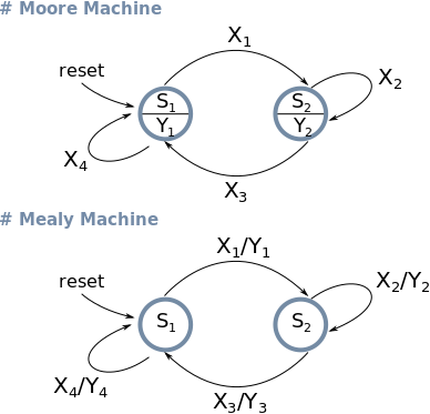
State diagram is the usual way of representing graphically systems with finite states — which is, obviously, the case for FSMs. A State diagram is a direct graph with edges representing the states and vertex representing the transitions. Figure 2 shows the state diagrams for both Moore and Mealy machines.
 |
| Figure 2: State diagrams for Moore and Mealy Machines. Xn = Input value | Yn = Output value. |
# A Simple Traffic Light with Logic Gates
Using the scheme in Figure 1 for the Moore machine, let's design a simple traffic light. This won't be a road intersection (even though can be easily expanded for that purpose) just a simple and easy circuit that displays different timing for each active light for cars and pedestrians.
Let's start with our state diagram.
 |
| Figure 3: Each bit in the output represents a different light (Red|Yellow|Green|Red|Green). |
As previously mentioned, to indicate the current state we need a way to store its value. In other words, that means we are going to make use of flip-flops to build our state memory.
Of course you can use any sort of flip-flop or even other types of memory, however, in order to make things simple, we are going to stick with D-type flip-flops. The excitation of a D flip-flop is very straightforward, it just holds the value of its D-input in a defined portion of the clock (rising or falling edge).
All right, now that we have our state diagram we can build our state transition table. Note that all the states are encoded in binary. The current state is represented in binary form on the output of the flip-flop (Qn) and the next-state in the input (Dn). The encoded format of the states also indicates that we will need to make use of three flip-flops.
All right, now that we have our state diagram we can build our state transition table. Note that all the states are encoded in binary. The current state is represented in binary form on the output of the flip-flop (Qn) and the next-state in the input (Dn). The encoded format of the states also indicates that we will need to make use of three flip-flops.
Table 1: State Transition Table
| State Name | State | Output | Next State | ||||||||
|---|---|---|---|---|---|---|---|---|---|---|---|
| Q0 | Q1 | Q2 | Y0 | Y1 | Y2 | Y3 | Y4 | D0 | D1 | D2 | |
| RESET | 0 | 0 | 0 | 0 | 0 | 0 | 0 | 0 | 0 | 0 | 1 |
| R0 | 0 | 0 | 1 | 1 | 0 | 0 | 0 | 1 | 0 | 1 | 0 |
| R1 | 0 | 1 | 0 | 1 | 0 | 0 | 0 | 1 | 0 | 1 | 1 |
| R2 | 0 | 1 | 1 | 1 | 0 | 0 | 0 | 1 | 1 | 0 | 0 |
| G0 | 1 | 0 | 0 | 0 | 0 | 1 | 1 | 0 | 1 | 0 | 1 |
| G1 | 1 | 0 | 1 | 0 | 0 | 1 | 1 | 0 | 1 | 1 | 0 |
| Y0 | 1 | 1 | 0 | 0 | 1 | 0 | 1 | 0 | 0 | 0 | 1 |
| - | 1 | 1 | 1 | X | X | X | X | X | X | X | X |
To derive our boolean expression for each output and each flip-flop we can apply the Karnaugh Map. Figure 4 shows the K-maps for the states and the outputs of our traffic light.
 |
| Figure 4: States and output boolean expressions extracted from K-map. |
Finally, all we have to do is place our flip-flops and logic gates from the expressions we got in Figure 4.
Using the website simulator.io I implemented a version of the final circuit we derived. You just have to generate a pulse to make transitions happen.
 |
| Figura 5: Schematic of our traffic light. |
That is it! We made it! But you shouldn't stop here. Finite-State Machines are great and they can be deployed almost everywhere, FPGAs, computer programming, logic gates, etc. Don't forget! Even though the concept of FSM is very simple, it doesn't mean that it is of little importance.
No comments:
Post a Comment